Parsing Direct3D shader bytecode
TL/DR
In this post, I will discuss the Direct3D shader bytecode format, and how to parse it without using the Direct3D API. This is basically a write-up of SlimShader, a .NET library that can read in Direct3D 10 / 11 HLSL bytecode and give you back the shader instructions and metadata as nicely structured objects.
- HLSL and Shader Model 4 / 5 assembly
- Parsing shader bytecode
- RDEF chunk
- ISGN chunk
- OSGN chunk
- SHDR chunk
- STAT chunk
- Other chunk types
- Conclusion
Warning: niche content ahead
This topic is not for everyone. More accurately, very few people will ever need to know any of this. The details of Direct3D’s shader bytecode format are really only useful to Microsoft and their hardware partners.
So why am I interested in understanding how HLSL shader bytecode works? The simple answer is: because it’s there.
The longer answer is: I got started on all of this while writing a software rasteriser - Rasterizr - and I wanted to use real HLSL shaders in the software rasterisation pipeline. I didn’t want to take a dependency on Direct3D - so instead, I figured out how to disassemble compiled HLSL shaders back to assembly instructions, and then I wrote a virtual machine that can execute these assembly instructions entirely on the CPU. I implemented both an interpreter and a JIT compiler (the JIT compiler actually has pretty good performance, although obviously it’s still orders of magnitude slower than a GPU). Admittedly, that was a huge amount of effort for what is mostly a pointless (albeit fun) project. Here’s a screenshot of the debugging GUI I built for Rasterizr.
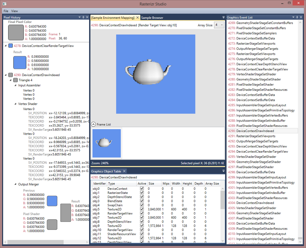
I intentionally modelled Rasterizr’s API (and debugging tools) on Direct3D - I wanted Rasterizr to serve as an educational tool, to help me (and perhaps others) understand what’s going on under the bonnet (or “hood”, if you speak Simplified English) in Direct3D.
Something vaguely useful did come out of my work on SlimShader - HlslUnit, a unit testing library for HLSL code.
If you’re still reading, I’ll assume you’re okay with the niche-ness of this topic. Let’s get started.
HLSL and Shader Model 4 / 5 assembly
The following code is a simple, but complete, HLSL vertex shader. We’ll be following this shader through compilation to binary bytecode. Then we’ll figure out how to parse the resulting binary, and extract the assembly instructions and metadata back out.
(A brief aside: we’ll stop our journey at bytecode; GPUs often have their own intermediate and assembly languages, but that differs from GPU to GPU and is lower-level than we’ll get into here.)
struct VertexShaderInput
{
    float3 pos : POSITION;
    float2 tex : TEXCOORD;
};

struct PixelShaderInput
{
    float4 pos : SV_POSITION;
    float2 tex : TEXCOORD;
};

float4x4 WorldViewProjection;

PixelShaderInput VS(VertexShaderInput input)
{
    PixelShaderInput output;

    output.pos = mul(float4(input.pos, 1), WorldViewProjection);
    output.tex = input.tex;

    return output;
}
Now let’s compile this shader using fxc.exe, the HLSL shader compiler:
fxc.exe /Fo TestShader.o /T vs_4_0 /E VS /nologo TestShader.hlsl
The /T parameter sets the target profile to vs_4_0, and the /E parameter sets the entry point function to VS.
Running that will compile the shader into TestShader.o, a binary file. This is the file that we’re going to be delving into.
Parsing shader bytecode
TestShader.o contains the compiled shader, and it’s what you’d use in your game when calling CreateVertexShader or CreatePixelShader.
Direct3D has a D3DDisassemble function which takes this compiled shader (as a byte array), and disassembles it back to the assembly instructions. Almost all of the time, that’s what you should use, if that’s what you want to do.
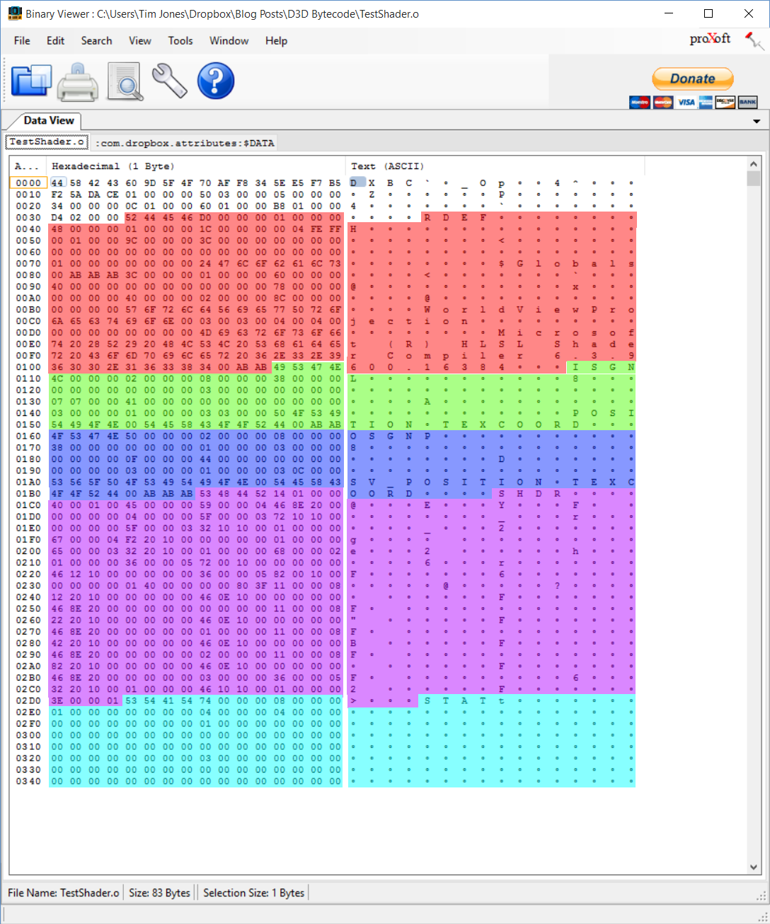
But that’s not what we want to do; we want to understand how this file is structured, and parse it ourselves. Let’s delve into this compiled shader file. Since this is a binary file, we’ll need a tool that helps us view binary files. I use Binary Viewer.
This is what Binary Viewer looks like after I open TestShader.o:

I’ve made the assumption that if you’ve got this far, you’re familiar with binary files - if not, have a look at Wikipedia’s entry on binary files.
Binary Viewer shows the raw bytes on the left, and the ASCII representation of those bytes on the right. Not all byte values are valid ASCII, which is why most of the values on the right use the ◦ placeholder. But the ASCII values that are present are interesting.
At the very beginning of the file, the first four bytes are 0x44 0x58 0x42 0x43. Those are the ASCII codes for the string “DXBC”. It turns out that every compiled HLSL shader starts with these four bytes. Looking at the rest of the file, we can see a number of bits of text that look relevant - we’ll get to those soon.
If you compile enough different shaders, and compare / contrast the resulting binaries, you see some patterns start to emerge. That’s the key to understanding how binary files like these are structured (unless of course someone helpfully provides you with the spec, but where would the fun be in that?).
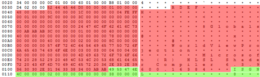
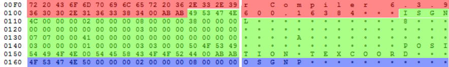
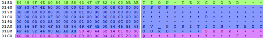
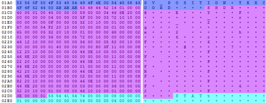
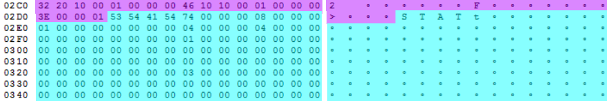
It turns out that compiled HLSL shaders are composed of a header, followed by a number of chunks. This is hinted at by the ASCII strings at the start of each chunk - in this case “RDEF”, “ISGN”, “OSGN”, “SHDR”, and “STAT”. You can see the chunks more clearly if I overlay each one with a different colour:
The uncoloured section at the beginning of the file is the header. The header contains information we’ll need to successfully parse the file, such as the location of the start of each chunk.
Here’s the structure of the header, including the specific values for our example shader. In the following tables, “byte offset” always means from the start of the file.
| Byte offset | Value | Description |
|---|---|---|
| 0-3 | “DXBC” | Always the string “DXBC” |
| 4-19 | 1331666272 888713072 3052922206 3470416626 |
Checksum; the HLSL compiler uses a private algorithm to compute this |
| 20-23 | 1 | Always the number “1” - I don’t know why this exists, perhaps as a sanity check |
| 24-27 | 848 | Total size, in bytes, of the compiled shader, including the header |
| 28-31 | 5 | Chunk count |
Next up is the chunk index. For each chunk, you get the offset (in bytes) of the start of that chunk. Our example shader has 5 chunks, so we have 5 entries in the chunk index. To aid in understanding, I’ve added the chunk type as well, but this isn’t part of the chunk index; the chunk type is declared at the start of each chunk.
| Byte offset | Byte address of start of chunk | Chunk type |
|---|---|---|
| 32-35 | 52 | RDEF |
| 36-39 | 268 | ISGN |
| 40-43 | 352 | OSGN |
| 44-47 | 440 | SHDR |
| 48-51 | 724 | STAT |
I keep using the word “chunk”, but what exactly does that mean? Chunks are used to break the data in the compiled shader into logical parts. Direct3D (probably) doesn’t always need to load every chunk; I’d guess, for example, that it doesn’t load the STAT chunk unless you use shader reflection APIs. Here are all the chunk types that I’ve seen:
| Chunk type | Description |
|---|---|
| ICFE | Interface. Describes any interfaces, and implementing classes, present in the source HLSL. |
| ISGN | Input signature |
| OSG5 | Output signature (SM5) |
| OSGN | Output signature |
| PCSG | Patch constant signature |
| RDEF | Resource definition. Describes constant buffers and resource bindings. |
| SDGB | Shader debugging info (old-style) |
| SFI0 | Not really sure… it stores a value that indicates whether double-precision floating point operations are enabled, but I don’t know why that needs to be in its own chunk |
| SHDR | Shader (SM4). The shader itself. |
| SHEX | Shader (SM5) |
| SPDB | Shader debugging info (new-style) |
| STAT | Statistics. Useful statistics about the shader, such as instruction count, declaration count, etc. |
SlimShader exposes all of the data in all of these chunks (except the debugging chunks) through a nice friendly object model. Direct3D exposes some of this data through the ID3D11ShaderReflection interface.
I figured out a lot of this stuff the hard way: I compiled multiple shaders, and looked for similarities and differences in the resulting binaries. I also got help from:
- The Nuclex Framework, in particular the HlslShaderReflector class, was very helpful when figuring out the RDEF, ISGN and OSGN chunks.
- The Wine project, in particular Wine’s shader reflection code, had some good tips for decoding the STAT chunk.
- For the SHDR chunk, I mostly just used
D3D11TokenizedProgramFormat.hpp, a header file that comes with the Windows Driver Kit (WDK).
Now that we’ve got an overview of how the file is structured, let’s turn our attention to parsing the individual chunks. I’m going to describe in detail the 5 chunks in our example compiled shader. If you want more details on the other chunk types, the SlimShader source code is a good place to start.
RDEF chunk
The first chunk in our example compiled shader is of type RDEF, or “resource definition”. Resource definition chunks are split into two main parts:
- Constant buffer descriptions. In our example, we have a single constant buffer named
$Globals, which contains a single variable namedWorldViewProjection, which is a 4x4 matrix. - Resource bindings. In our example, we only have a single constant buffer, but this is where you would find bindings for textures, samplers, structured buffers, etc.
Looking at the chunk index table above, we see that the byte address of the start of the first chunk is 52. Using Binary Viewer, we start looking at the byte values starting at index 52. (If you were doing this from scratch, you’d have to painstakingly compare / contrast shader binaries until you could guess at what each value means.) Note that most of these values are stored in the binary file as 32-bit uints, so we mostly, but not always, need to read 4 bytes at a time.
| Byte offset | Value | Description |
|---|---|---|
| 52-55 | “RDEF” | Indicates that this is a RDEF (resource definition) chunk |
| 56-59 | 208 | Length of the chunk, in bytes |
| 60-63 | 1 | Constant buffer count |
| 64-67 | 72 | Byte offset (from start of chunk data, after chunk type and chunk length) to first constant buffer description |
| 68-71 | 1 | Resource binding count |
| 72-75 | 28 | Byte offset (from start of chunk data) to first resource binding description |
| 76 | 0 | Minor version number |
| 77 | 4 | Major version number |
| 78-79 | 0xFFFE | Program type. “0xFFFE” means vertex shader. |
| 80-83 | 256 | Flags. “256” means “NoPreshader”. |
| 84-87 | 156 | Byte offset (from start of chunk data) to “creator” string |
In this blog post, I’m only describing Shader Model 4.0 shaders. Shader Model 5.0 shaders contain some additional data; SlimShader supports both SM 4.0 and SM 5.0.
A number of values in the data that follows are byte offsets from the “start of chunk data”. The start of the chunk data is the byte immediately following the chunk length. In this RDEF chunk, that is the byte at offset 60 from the beginning of the file.
Now we’ve parsed the “header” portion of the RDEF chunk. It’s time to parse the “body”, which is composed of constant buffer and resource binding descriptions. We know from the header that the first constant buffer description can be found at byte address 60 + 72 = 135 (60 is the address of the start of the chunk data, and 72 is the offset to the first constant buffer). So let’s see what’s in the constant buffer description:
| Byte offset | Value | Description |
|---|---|---|
| 132-135 | 60 | Byte offset (from start of chunk data) to constant buffer name |
| 136-139 | 1 | Variable count |
| 140-143 | 96 | Byte offset (from start of chunk data) to first variable description |
| 144-147 | 64 | Size of the constant buffer, in bytes |
| 148-151 | 0 | Flags, based on D3D_SHADER_CBUFFER_FLAGS |
| 152-155 | 0 | Constant buffer type, based on D3D11_CBUFFER_TYPE |
According to the table above, the constant buffer name will be found at 60 + 60 = 120. Strings are null-terminated, so we keep reading until we reach a 0:
| Byte offset | Value | Description |
|---|---|---|
| 120 | “$Globals” | Constant buffer name |
Now let’s parse the variables for this constant buffer. In this case, there is only one constant buffer, which contains one variable. We know from the table above that the variable description starts at 60 + 96 = 156.
| Byte offset | Value | Description |
|---|---|---|
| 156-159 | 120 | Byte offset (from start of chunk data) to variable name |
| 160-163 | 0 | Offset from start of constant buffer (in bytes) |
| 164-167 | 64 | Variable size (in bytes) |
| 168-171 | 2 | Variable flags, based on D3D10_SHADER_VARIABLE_FLAGS. 2 means this variable is used in the shader. |
| 172-175 | 140 | Byte offset (from start of chunk data) to variable type |
| 176-179 | 0 | Byte offset (from start of chunk data) to default value. “0” means there isn’t a default value. |
Let’s parse the variable name, at address 60 + 120 = 180:
| Byte offset | Value | Description |
|---|---|---|
| 180 | “WorldViewProjection” | Variable name |
And then the variable type, at address 60 + 140 = 200:
| Byte offset | Value | Description |
|---|---|---|
| 200-201 | 3 | Variable class, based on D3D10_SHADER_VARIABLE_CLASS. “3” means the variable is a column-major matrix. |
| 202-203 | 3 | Variable type, based on D3D10_SHADER_VARIABLE_TYPE. “3” means the variable is a floating-point number. |
| 204-205 | 4 | Number of rows in matrix-type variables |
| 206-207 | 4 | Number of columns in matrix-type variables |
| 208-209 | 0 | Number of elements in array-type variables |
| 210-211 | 0 | Number of members in structure-type variables |
| 212-213 | 0 | Byte offset (from start of chunk data) to first member |
Whew! As you can see, there are a lot of different structures contained in HLSL shader binaries. And this is just the RDEF chunk type! We’re nearly there though. Next, let’s parse the resource binding description. Going back to the first table in this section, we see that the first resource binding description can be found at address 60 + 28 = 88.
| Byte offset | Value | Description |
|---|---|---|
| 88-91 | 60 | Byte offset (from start of chunk data) to resource binding name |
| 92-95 | 0 | Shader input type. “0” means cbuffer. |
| 96-99 | 0 | Resource return type. “0” means not applicable. |
| 100-103 | 0 | Resource view dimension. “0” means not applicable. |
| 104-107 | 0 | Number of samples |
| 108-111 | 0 | Bind point |
| 112-115 | 1 | Bind count |
| 116-119 | 0 | Shader input flags |
One interesting thing to note is that the data is very efficiently packed in the binary file. There are very few, if any, wasted bytes. You would expect nothing less, but still, it’s nice to see this attention to detail firsthand.
We have one last thing to parse from the RDEF chunk - the “creator”. We can find this at address 60 + 156 = 216:
| Byte offset | Value | Description |
|---|---|---|
| 216 | “Microsoft (R) HLSL Shader Compiler 6.3.9600.16384” | Creator |
After all of that work, we know enough to reconstruct this line from our original HLSL code:
float4x4 WorldViewProjection;
But we also know a bit more than that; we know that:
- the HLSL compiler automatically put this variable into a
cbuffercalled$Globals - it is a column-major matrix
- it is referenced in the shader
ISGN chunk
ISGN chunks define the input signature for a shader. For a vertex shader like this one, the input signature describes the shape of the data coming from the application.
ISGN chunks are much simpler than RDEF chunks. Here’s how the ISGN header is structured:
| Byte offset | Value | Description |
|---|---|---|
| 268-271 | “ISGN” | Indicates that this is a RDEF (resource definition) chunk |
| 272-275 | 76 | Length of the chunk, in bytes |
| 276-279 | 2 | Element count |
| 280-283 | 8 | I don’t know what this is used for… |
The element data immediately follows the ISGN header. We have 2 elements, with these values:
| Byte offset | Value | Description |
|---|---|---|
| 284-287 | 56 | Byte offset (from start of chunk data) to element name |
| 288-291 | 0 | Semantic index |
| 292-295 | 0 | System value type |
| 296-299 | 3 | Component type. “3” means floating-point |
| 300-303 | 0 | Register |
| 304 | 7 | Mask. “7” means XYZ, which means this is a 3-component vector. |
| 305 | 7 | Read-write mask. This is the same as the mask, but it is also possible for not all components to actually be used by the shader. |
| Byte offset | Value | Description |
|---|---|---|
| 332 | “POSITION” | Element name |
| Byte offset | Value | Description |
|---|---|---|
| 308-311 | 65 | Byte offset (from start of chunk data) to element name |
| 312-315 | 0 | Semantic index |
| 316-319 | 0 | System value type |
| 320-323 | 3 | Component type. “3” means floating-point |
| 324-327 | 1 | Register |
| 328 | 3 | Mask. “3” means XY, which means this is a 2-component vector. |
| 329 | 3 | Read-write mask |
| Byte offset | Value | Description |
|---|---|---|
| 341 | “TEXCOORD” | Element name |
And that’s it! The input signature chunk tells us the structure of data coming into the shader:
- A
float3parameter whose semantic isPOSITION, assigned to register0 - A
float2parameter whose semantic isTEXCOORD, assigned to register1
Compare this to the original HLSL:
struct VertexShaderInput
{
    float3 pos : POSITION;
    float2 tex : TEXCOORD;
};
We’ve lost some information - such as the name of the struct, and the names of the struct fields. Those names aren’t needed by the GPU. Instead, the HLSL compiler has assigned register numbers to these two values.
OSGN chunk
OSGN chunks define the output signature for a shader. For a vertex shader like this, the output signature describes the shape of the data being output from the vertex shader to the pixel shader (or geometry shader, or hull shader).
Happily, OSGN chunks are structured in exactly the same way as ISGN chunks. So I’ll skip to the end and show you the parsed information. The output signature for this example shader is:
- A
float4parameter whose semantic isSV_POSITION, assigned to register0 - A
float2parameter whose semantic isTEXCOORD, assigned to register1
Again, compare that to the original HLSL:
struct PixelShaderInput
{
    float4 pos : SV_POSITION;
    float2 tex : TEXCOORD;
};
We’ve kept the important information, and the HLSL compiler has assigned registers to each value in the output.
SHDR chunk
The SHDR chunk is, as you might guess, where the actual shader can be found. The other chunks are basically metadata; the SHDR chunk is where you find the declarations and instructions that make up the shader itself.
It is, by far, the most complicated chunk to parse. But fortunately, it’s also the (only) chunk type that is publicly documented. If you install the Windows Driver Kit (WDK), you get a file that describes the binary format in some detail, usually located here:
C:\Program Files (x86)\Windows Kits\10\Include\10.0.10240.0\um\d3d11TokenizedProgramFormat.hpp
Because the documentation for the binary format of the SHDR chunk is readily available, I won’t go into too much detail.
Briefly, the SHDR chunk, in common with the other chunk types, is composed of a header and a body. The header is structured as follows:
| Byte offset | Value | Description |
|---|---|---|
| 440-443 | “SHDR” | Indicates that this is a SHDR (shader) chunk |
| 444-447 | 276 | Length of the chunk, in bytes |
| 448 (low 4 bits) | 0 | Minor version number |
| 448 (high 4 bits) | 4 | Major version number |
| 450-451 | 1 | Program type. “1” means vertex shader. |
| 452-455 | 69 | Number of DWORDs in the chunk |
After the header come a sequence of “opcodes”. Opcodes are the binary representation of shader assembly instructions. You can see the full list of Shader Model 5 assembly instructions here. Opcodes represent both declarations (i.e. texture declarations, constant buffer declarations, etc.) and instructions (i.e. add, multiply, etc.).
Each opcode has its own binary structure, but there are some commonalities. Here’s the section of d3d11TokenizedProgramFormat.hpp that tells us how to read the first token of each opcode.
// ----------------------------------------------------------------------------
// Opcode Format (OpcodeToken0)
//
// [10:00] D3D10_SB_OPCODE_TYPE
// if( [10:00] == D3D10_SB_OPCODE_CUSTOMDATA )
// {
//    Token starts a custom-data block.  See "Custom-Data Block Format".
// }
// else // standard opcode token
// {
//    [23:11] Opcode-Specific Controls
//    [30:24] Instruction length in DWORDs including the opcode token.
//    [31]    0 normally. 1 if extended operand definition, meaning next DWORD
//            contains extended opcode token.
// }
//
// ----------------------------------------------------------------------------
So every opcode stores the opcode type in the first 10 bits. Once you’ve read the type, you use that to know how to parse the rest of the opcode.
As an example, let’s look at the first opcode from our example shader.
| Byte offset | Value | Description |
|---|---|---|
| 456-459 (bits 0 to 10) | 89 | Opcode type |
| 456-459 (bits 24 to 30) | 4 | Opcode length |
| 456-459 (bit 31) | 0 | 1 if opcode is “extended”, otherwise 0 |
Looking at D3D10_SB_OPCODE_TYPE in d3d11TokenizedProgramFormat.hpp, we see that opcode type 89 equates to D3D10_SB_OPCODE_DCL_CONSTANT_BUFFER. So then we look further down the file to find how constant buffer declaration opcodes are structured:
// ----------------------------------------------------------------------------
// Constant Buffer Declaration
//
// OpcodeToken0:
//
// [10:00] D3D10_SB_OPCODE_DCL_CONSTANT_BUFFER
// [11]    D3D10_SB_CONSTANT_BUFFER_ACCESS_PATTERN
// [23:12] Ignored, 0
// [30:24] Instruction length in DWORDs including the opcode token.
// [31]    0 normally. 1 if extended operand definition, meaning next DWORD
//         contains extended operand description.  This dcl is currently not
//         extended.
//
// OpcodeToken0 is followed by 1 operand:
// (1) Operand, starting with OperandToken0, defining which CB slot (cb#[size])
//     is being declared. (operand type: D3D10_SB_OPERAND_TYPE_CONSTANT_BUFFER)
//     The indexing dimension for the register must be
//     D3D10_SB_OPERAND_INDEX_DIMENSION_2D, where the first index specifies
//     which cb#[] is being declared, and the second (array) index specifies the size
//     of the buffer, as a count of 32-bit*4 elements.  (As opposed to when the
//     cb#[] is used in shader instructions, and the array index represents which
//     location in the constant buffer is being referenced.)
//     If the size is specified as 0, the CB size is not known (any size CB
//     can be bound to the slot).
//
// The order of constant buffer declarations in a shader indicates their
// relative priority from highest to lowest (hint to driver).
//
// ----------------------------------------------------------------------------
So for a constant buffer declaration, after the initial opcode token, we can expect to find a single operand, which defines which constant buffer slot is being declared. Operands are actually fairly complicated to parse. On the bright side, there’s a standard operand structure shared across all opcodes. But because it’s too hard (and I’m lazy), I’ll just point you at the Operand source code in SlimShader.
If we were to parse the operand, we’d be able to extract this assembly instruction:
dcl_constantbuffer cb0[4], immediateIndexed
We can then continue to parse all the remaining opcodes in the shader chunk. When writing SlimShader, I went through all the opcodes documented in d3d11TokenizedProgramFormat.hpp, and wrote the parsing logic for each one. For our example shader, we’d end up with these assembly instructions:
dcl_constantbuffer cb0[4], immediateIndexed
dcl_input v0.xyz
dcl_input v1.xy
dcl_output_siv o0.xyzw, position
dcl_output o1.xy
dcl_temps 1
mov r0.xyz, v0.xyzx
mov r0.w, l(1.000000)
dp4 o0.x, r0.xyzw, cb0[0].xyzw
dp4 o0.y, r0.xyzw, cb0[1].xyzw
dp4 o0.z, r0.xyzw, cb0[2].xyzw
dp4 o0.w, r0.xyzw, cb0[3].xyzw
mov o1.xy, v1.xyxx
ret
There are 6 declarations, and 8 instructions. When you use a shader in Direct3D, these assembly instructions are parsed from the bytecode (much like we’re doing here), and sent to the GPU. Somewhere along the way (presumably in the GPU driver), the Direct3D assembly instructions will be compiled (again) into the GPU’s own assembly language, which is lower-level and hardware-specific.
In older versions of Direct3D, you could author shaders using assembly instructions, but that hasn’t been possible for a while. These days you need to use HLSL (which is fine by me, I have enough trouble reading assembly code, let alone writing it).
STAT chunk
The STAT chunk is the least interesting chunk type (“interesting” might be a poor choice of word in a topic as dry as this one, but work with me). I don’t imagine it’s used in the Direct3D runtime, unless you use the ID3D11ShaderReflection interface.
Here’s the data in the STAT chunk in our example shader. I’ve guessed at what some of these values mean, and some I just don’t know, despite comparing and contrasting multiple shader binaries.
| Byte offset | Value | Description |
|---|---|---|
| 724-727 | “STAT” | Indicates that this is a STAT (statistics) chunk |
| 728-731 | 116 | Length of the chunk, in bytes |
| 732-735 | 8 | Instruction count |
| 736-739 | 1 | Temp register count |
| 740-743 | 0 | Define count |
| 744-747 | 4 | Declaration count |
| 748-751 | 4 | Float instruction count |
| 752-755 | 0 | Int instruction count |
| 756-759 | 0 | Uint instruction count |
| 760-763 | 1 | Static flow control count |
| 764-767 | 0 | Dynamic flow control count |
| 768-771 | 0 | Macro instruction count - maybe? I guessed this |
| 772-775 | 0 | Temp array count |
| 776-779 | 0 | Array instruction count |
| 780-783 | 0 | Cut instruction count |
| 784-787 | 0 | Emit instruction count |
| 788-791 | 0 | Texture normal instructions |
| 792-795 | 0 | Texture load instructions |
| 796-799 | 0 | Texture comparison instructions |
| 800-803 | 0 | Texture bias instructions |
| 804-807 | 0 | Texture gradient instructions |
| 808-811 | 3 | Mov instruction count |
| 812-815 | 0 | Movc instruction count |
| 816-819 | 0 | Conversion instruction count |
| 820-823 | 0 | ? - No idea… |
| 824-827 | 0 | Input primitive for geometry shaders |
| 828-831 | 0 | Primitive topology for geometry shaders |
| 832-835 | 0 | Max output vertex count for geometry shaders |
| 836-839 | 0 | ? - No idea… |
| 840-843 | 0 | ? - No idea… |
| 844-847 | 0 | 1 for sample frequency shader, otherwise 0 |
This data is exposed in Direct3D through a combination of D3D11_SHADER_DESC and ID3D11ShaderReflection methods.
Other chunk types
There are several other chunk types not found in our example shader. The other chunk types supported by SlimShader are:
- IFCE - InterfacesChunk.cs
- SFI0 - Sfi0Chunk.cs
- PCSG - PatchConstantSignatureChunk.cs
Conclusion
That was pretty heavy going! But I didn’t think it was worth writing this blog post without going fairly deep into the details. If you found it useful, or have questions, or can fill in any of the gaps in my knowledge, please leave a comment!
I hope to write a follow-up post describing how I used this bytecode parser to build a virtual machine that can execute Direct3D bytecode entirely on the CPU, in managed code. Stay tuned!